Trends
Sci.
2026;
23(8):
12657
Optimization of Operational Parameters in Nickel–Cobalt Electrowinning from Mixed Sulfate Electrolytes
Subandrio Subandrio1,2, Nur Lestari Widodo1, Andi Mutia Putri Kirana2,
Ade Irma Rozafia1, Nur Karimah1, Nor Farida1, Wiwik Dahani2, Afifah Rosyidah1,
Wahyu Prasetyo Utomo1 and Djoko Hartanto1,*
1Laboratory of Material Chemistry and Energy, Department of Chemistry, Faculty of Science and Data Analytics, Institut Teknologi Sepuluh Nopember (ITS), Surabaya 60111, Indonesia
2Mining Engineering Study Programe, Faculty of Earth and Energy Technology, University of Trisakti, Grogol Petamburan, West Jakarta 11440, Indonesia
(*Corresponding author’s e-mail: [email protected])
Received: 14 November 2025, Revised: 22 December 2025, Accepted: 29 December 2025, Published: 10 March 2026
Abstract
Nickel and cobalt are strategic metals that play an important role in the development of electric vehicle batteries and high-performance metal alloys. Indonesia, as one of the countries with the largest laterite nickel reserves in the world, faces challenges in the efficient, selective, and environmentally friendly extraction process. Conventional separation methods such as solvent extraction have drawbacks, including high cost and the chemical waste generated. Therefore, the electrowinning method becomes a promising alternative because it can produce high-purity metals with lower energy consumption. This research aims to optimize the process of electrowinning mixed nickel and cobalt from sulfate solution by varying electrode distance, applied potential, and metal ion concentration ratio to improve deposition efficiency and selectivity of the resulting metals. The process was conducted using a batch electrolysis cell with nickel-cobalt sulfate electrolyte and boric acid buffer. The research results indicate that increasing the potential and decreasing the electrode distance significantly increase the mass of the metal deposit, whereas the Ni-Co concentration ratio affects reduction selectivity due to differences in ion mobility and overpotential for each metal. XRD analysis shows that the crystal phase formed is dominated by nickel with a face-centered cubic (FCC) structure and cobalt with a hexagonal close-packed (HCP) structure. Increasing the potential leads to a decrease in crystallinity due to the high nucleation rate. FESEM observation results show that the particle morphology is non-uniform with a flower-like aggregate shape, while EDX analysis indicates that the deposit composition is dominated by nickel at 86.9% and cobalt at 13.1% with uniform element distribution. These results indicate that optimal electrowinning conditions are capable of producing homogeneous nickel and cobalt metal deposits with high efficiency.
Keywords: Nickel, Cobalt, Electrowinning, Potential, Industrialization
Introduction
Nickel is a naturally occurring metallic element in the Earth’s crust that plays a crucial role in modern industry due to its unique physical and chemical properties [1,2]. The demand for nickel continues to rise with the advancement of electric vehicle battery technology. In addition, nickel is widely utilized as an alloying material in construction and household
applications [3,4]. Generally, nickel occurs as a silvery-white metal and ranks as the fifth most abundant element on Earth, distributed across various environments including air, water, and soil in diverse mineral forms [5]. According to the United States Geological Survey (USGS), Indonesia possesses the largest nickel reserves in the world [6]. Meanwhile, cobalt is considered a critical metal in the global market due to its limited availability and extensive industrial applications. Similar to nickel, the demand for cobalt has rapidly increased in line with the growth of the electric vehicle industry, contributing significantly to global economic development [7,8]. Therefore, the extraction and processing of both metals are of strategic importance to support Indonesia’s economic growth.
Laterite ore serves as a primary source of nickel and cobalt metals. Typically, this ore is processed using the hydrometallurgical method, an extraction technique consisting of several key stages, namely leaching, precipitation, and electrowinning [5]. The hydrometallurgical approach is widely preferred due to its relatively low energy consumption and reduced environmental pollution compared to pyrometallurgical processes. In this method, metal purification can be achieved through various techniques such as electrowinning, hydrogen sulphide reduction, solvent extraction, and carbon reduction [1,2,9]. Among these, electrowinning is recognized as an efficient method for nickel and cobalt purification, producing high-purity metals under low-temperature conditions without the need for high-pressure gas. However, the success of the electrowinning process strongly depends on precise control of operational parameters to ensure consistent metal deposition. Therefore, improving production efficiency and minimizing environmental impact have become key objectives in optimizing the electrowinning process for nickel and cobalt extraction [8,10].
Sudibyo et al. [11] investigated the application of the electro metal electrowinning (EMEW) method to recover nickel metal from laterite ore leach solutions [11]. The study optimized the operating parameters using the Taguchi method to determine the most effective conditions influencing nickel deposition efficiency. The variables examined included temperature, applied voltage, electrolysis duration, and boric acid concentration in the electrolyte. The optimum conditions were found at 60 °C, 2 V, 6 h, and 0.5 M boric acid, yielding a high-purity nickel deposit. This study demonstrated that operational optimization using the Taguchi approach significantly enhances the efficiency and quality of the EMEW process, highlighting its potential for hydrometallurgical nickel recovery from laterite ores [11].
Moreover, the electrochemical parameters applied during the electrowinning process strongly affect the morphology and type of deposit formed at the cathode. Shi et al. [12] conducted nickel electrowinning from electronic waste leachates [12]. Under optimal conditions, the process produced three types of nickel deposits: Green Ni(OH)2 powder, black nickel powder, and silvery metallic flakes. Ni(OH)2 was obtained at 125 A/m2 with a concentration of 0.05 M for 1.5 h; black nickel powder formed at 60 A/m2, 0.1 M, for 2 h; and silvery nickel flakes were produced at 125 A/m2, 0.25 M, for 2 h. The study indicated that increasing the current density led to poorer solid quality, emphasizing the need for strict process control to achieve optimal results.
Similarly, cobalt electrowinning has also been investigated by several researchers. Passos et al. [8] examined the influence of current density and pH on cobalt electrowinning [8]. The electrolyte consisted of 60 g/L CoSO4 with varying pH levels of 3, 4, and 5, prepared with Na2SO4, H3BO3, and Sodium Lauryl Sulfate as additives. The results revealed that at pH 3 and 4, the cobalt deposits were rough and contained pits due to hydrogen evolution at the cathode surface. The most favourable condition was obtained at pH 5 and a current density of 400 A/m2, which produced smooth and uniform cobalt deposits.
Kazem et al. [13] conducted separate electrowinning experiments for nickel and cobalt from sulfate solutions under a non-circulating system [13]. The electrolyte solution was supplemented with boric acid as a buffering agent. The study investigated the effects of initial pH, current density, and temperature, with electrolysis durations of 30 and 60 min. The optimal conditions for nickel electrowinning were obtained at a current density of 400 A/m2, temperature of 55 °C, and initial pH of 5, yielding a current efficiency of 78.32% and an energy consumption of 3.44 kWh/kg. These conditions produced high-quality nickel deposits characterized by uniform morphology, low surface roughness, and minimal hydrogen-induced porosity. Conversely, suboptimal results were obtained at 500 A/m2, 75 °C, and pH 6, which produced coarse and cracked deposits with higher energy consumption (3.91 kWh/kg). For cobalt electrowinning, the optimal conditions were achieved at 600 A/m2, 70 °C, and pH 5, with a current efficiency of 88.06% and energy consumption of 3.15 kWh/kg, resulting in smooth and bright cobalt deposits. However, less favourable results were observed at 800 A/m2, 80 °C, and pH 1.5, where current efficiency dropped to 49.65% and energy consumption increased to 5.65 kWh/kg, producing rough and brittle deposits.
Currently, nickel and cobalt electrowinning processes are typically conducted separately. In laterite ore processing industries, the separation of Ni and Co is predominantly achieved through solvent extraction using organic reagents, which are costly and environmentally hazardous if not properly treated [9]. Therefore, optimizing electrowinning parameters offers a promising, eco-friendly alternative to minimize solvent use and improve the efficiency of nickel–cobalt separation and purification [14]. In this study, the electrowinning of nickel and cobalt was carried out on a laboratory scale by controlling several operational parameters, including electrode distance, applied potential, and the concentration ratio of Ni and Co ions. Based on the standard reduction potentials (E0 Ni2+/Ni = –0.257 V vs SHE; E0 Co2+/Co = –0.280 V vs SHE) [10,15], the two metals exhibit closely similar electrochemical behaviour. Therefore, precise control of the applied potential is crucial to obtain high-quality and high-yield deposits of nickel and cobalt. Additionally, variations in electrode spacing and ion concentration were implemented to optimize the electrowinning process and maximize the deposition mass. These parameters are expected to influence the process efficiency, surface morphology, and phase formation of the deposited metals. The solid deposits on the cathode were characterized using X-Ray Diffraction (XRD) and X-Ray Fluorescence (XRF) to identify their crystalline structure and chemical composition.
Materials and methods
Materials
The materials used in this study included nickel sulfate hexahydrate (NiSO4·6H2O, plating grade, Sumitomoex Japan), cobalt sulfate heptahydrate (CoSO4·7H2O, plating grade, Sigma Aldrich), boric acid (H3BO3, for analysis, Merck), and distilled water (Brataco, Indonesia). These reagents were selected for their high purity to ensure reproducibility and accuracy in the electrowinning process. The main equipment utilized in this research comprised a DC power supply (Sanfix SP-6010, 60 V/10 A, Taiwan) as the current source, and an acrylic bath with a total capacity of 175 mL for the electrowinning cell. A high-purity copper plate (99.9%) with dimensions 3×5×0.2 cm3 was used as the cathode, while a carbon plate served as the anode. Additional apparatus included electrical alligator clips, a 500 mL volumetric flask, beakers, a hotplate, metal spatula, magnetic stirrer, and a thermometer (0 - 100 °C) for temperature monitoring. The universal pH indicator was employed to measure the initial and final pH values of the electrolyte solution during the electrowinning process.
Electrowinning procedure
This study was conducted experimentally on a laboratory scale to investigate the effects of applied potential, electrode distance, and the Ni - Co concentration ratio on the deposited mass and selectivity of the electrowinning process from mixed nickel - cobalt sulfate solutions. The electrowinning was performed in a batch electrolysis cell containing Ni-Co sulfate electrolyte with boric acid (H3BO3) added as a pH buffer. The research focused solely on the electrochemical deposition stage without involving further metal purification steps.
The electrolyte solution was prepared by dissolving nickel sulfate (NiSO4·6H2O) and cobalt sulfate (CoSO4·7H2O) in demineralized water. Nickel concentrations were varied at 11,610.00, 14,721.33, 17,028.67, and 20,124.67 mg·L−1, while cobalt concentration was kept constant at 1,677.33 mg·L−1. Boric acid was added at 30,000 mg·L−1 to maintain pH stability during the process. The electrowinning experiments employed an inert carbon anode and a pure copper cathode that were pre-cleaned, dried, and weighed as the initial mass. The electrode distances were varied at 8 and 12 cm, and the applied voltages were set at 8 and 14 V, with a constant electrolysis time of 120 min, following previous studies [11], is shown in Table 1. During the process, current and voltage were periodically monitored to ensure system stability. After electrolysis, the cathode deposits were rinsed with demineralized water, dried, and weighed to determine the deposited mass.
Table 1 Condition of electrowinning.
Condition |
Potensial (V) |
Electrode distance (cm) |
Ni: Co Concentration ratio |
Nickel (mg·L−1) |
Cobalt (mg·L−1) |
1 |
8 |
8 |
6.9:1 |
11,610.00 |
1,677.33 |
2 |
8.8:1 |
14,721.33 |
1,677.33 |
||
3 |
10.4:1 |
17,028.67 |
1,677.33 |
||
4 |
12:1 |
20,124.67 |
1,677.33 |
||
5 |
12 |
6.9:1 |
11,610.00 |
1,677.33 |
|
6 |
8.8:1 |
14,721.33 |
1,677.33 |
||
7 |
10.4:1 |
17,028.67 |
1,677.33 |
||
8 |
12:1 |
20,124.67 |
1,677.33 |
||
9 |
14 |
8 |
6.9:1 |
11,610.00 |
1,677.33 |
10 |
8.8:1 |
14,721.33 |
1,677.33 |
||
11 |
10.4:1 |
17,028.67 |
1,677.33 |
||
12 |
12:1 |
20,124.67 |
1,677.33 |
||
13 |
12 |
6.9:1 |
11,610.00 |
1,677.33 |
|
14 |
8.8:1 |
14,721.33 |
1,677.33 |
||
15 |
10.4:1 |
17,028.67 |
1,677.33 |
||
16 |
12:1 |
20,124.67 |
1,677.33 |
Materials characterization
The crystalline phases of the electrowinning products were characterized using X-Ray Diffraction (XRD, Rigaku Miniflex 600). The analysis employed Cu Kα radiation (λ = 1.5406 Å) at an operating voltage of 40 kV and a current of 15 mA. Diffraction data were collected in the 2θ range of 5° - 90° with a scan step size of 0.0170°. The resulting diffractograms represented the relationship between diffraction peak intensity and 2θ angle [16].
The surface morphology and particle size of the deposit materials were examined using Field Emission Scanning Electron Microscopy (FESEM Hitachi Regulus 8220). Sample preparation involved placing a small amount of the deposit onto a carbon-coated pin, followed by Pd/Au sputter coating to enhance conductivity. The analysis was conducted at an accelerating voltage of 15 kV using a secondary electron (SE) detector [17]. The obtained FESEM micrographs were further processed using the ImageJ software. In addition, the elemental composition of the deposits was determined using Energy Dispersive X-ray Spectroscopy (EDX) to quantify the Ni and Co contents [18]. The deposited solids were characterized using X-Ray Fluorescence (XRF) to determine the elemental composition of the metallic deposits. The XRF technique operates based on the emission of secondary X-rays from atoms excited by primary X-ray radiation. This analysis allows the quantitative determination of nickel and cobalt percentages in the electrowinning deposits.
Results and discussion
Electrowinning of nickel and cobalt
Nickel and cobalt electrowinning are a reduction process in which Ni2+ and Co2+ ions are converted into their metallic forms at the cathode surface. A copper plate is used as the cathode, while an inert carbon plate serves as the anode. During the process, a DC power supply transfers electrons from the negative to the positive terminal, enabling the reduction of metal ions in the electrolyte at the cathode. Boric acid is added as a buffering agent to maintain the pH stability of the electrolyte throughout the electrowinning process [19,20]. Boric acid in solution does not react at either the cathode or the anode because it only acts as a pH buffer. The ionization of nickel and cobalt is highly sensitive to pH variations; high pH leads to the formation of metal hydroxide precipitates, while excessively low pH enhances hydrogen evolution at the cathode, reducing current efficiency. The presence of boric acid stabilizes the electrolyte, ensuring a more efficient and controlled electrowinning process. The schematic of nickel and cobalt electrowinning is illustrated in Figure 1.
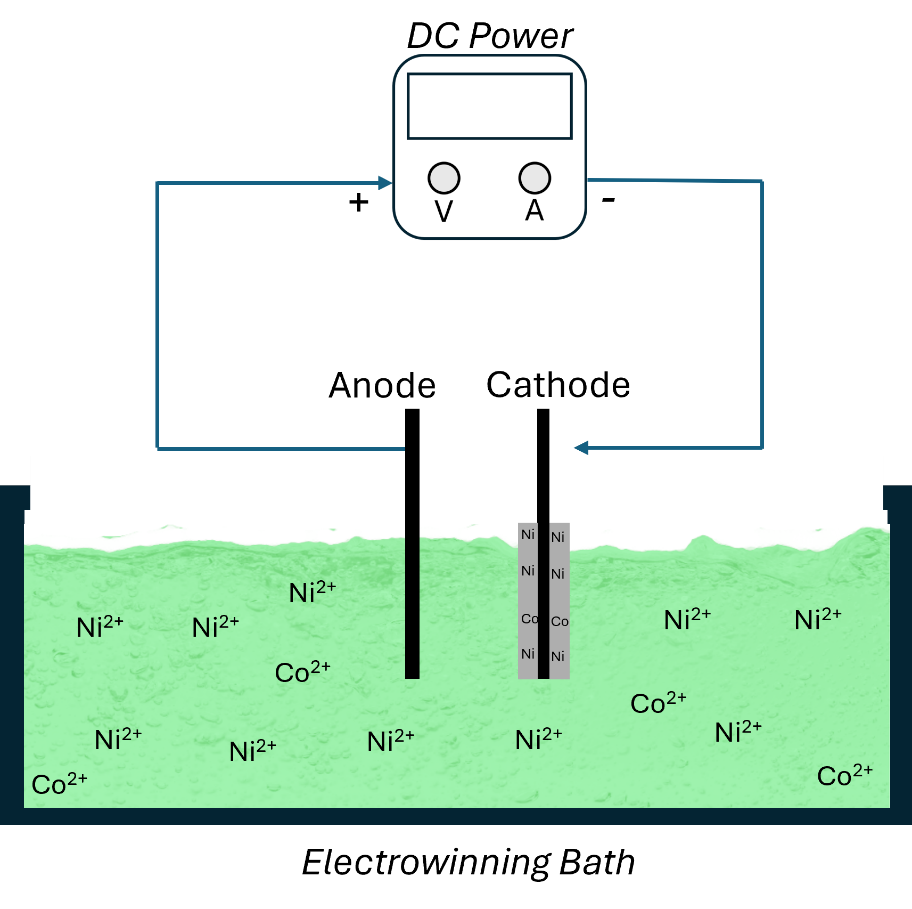
Figure 1 Scheme of electrowinning method.
Nickel and cobalt ions (Ni2+ and Co2+) in the electrolyte are reduced to metallic Ni and Co on the cathode surface. Conversely, at the anode, an oxidation reaction occurs, producing oxygen gas (O2) and hydrogen ions (H+) in the electrolyte. The possible reduction reactions at the cathode, involving Ni2+ and Co2+, are presented in Eqs. (1) - (5), while the oxidation reaction at the anode is shown in Eq. (6) [12]. While the deposit mass obtained in various parameters is tabulated in Table 2.
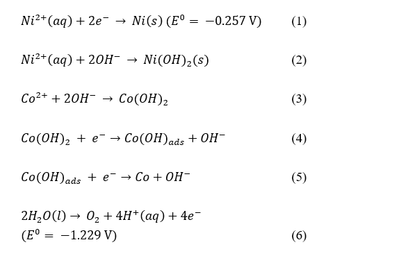
In addition to these main reactions, a side reaction involving hydrogen evolution may occur during the electrowinning process. This side reaction takes place because the standard reduction potential of hydrogen is more positive than that of nickel, making hydrogen reduction more thermodynamically favorable than nickel deposition (E0 = 0.00 V vs. SHE) [21]. The reduction of H+ to hydrogen gas (H2) is represented in Eq. (7). The hydrogen evolution reaction is undesirable as it consumes electrical energy and current inefficiently, while also degrading the morphology and quality of the deposited nickel layer [5,22].
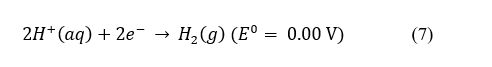
Table 2 Mass of deposits from nickel–cobalt electrowinning.
No. |
Electrode distance |
Variation of Ni:Co |
Concentration |
Deposit Mass |
||
Ni |
Co |
8 V |
14 V |
|||
cm |
(mg·L−1) |
(mg·L−1) |
(mg) |
(mg) |
||
1 |
8 |
6.9:1 |
11,610.00 |
1,677.33 |
1,372.90 |
1,599.00 |
2 |
8.8:1 |
14,721.33 |
1,677.33 |
1,615.60 |
2,984.40 |
|
3 |
10.4:1 |
17,028.67 |
1,677.33 |
1,676.20 |
1,804.30 |
|
4 |
12:1 |
20,124.67 |
1,677.33 |
1,830.60 |
4,354.90 |
|
5 |
12 |
6.9:1 |
11,610.00 |
1,677.33 |
1,025.30 |
1,863.90 |
6 |
8.8:1 |
14,721.33 |
1,677.33 |
1,218.80 |
2,353.80 |
|
7 |
10.4:1 |
17,028.67 |
1,677.33 |
1,213.20 |
2,400.30 |
|
8 |
12:1 |
20,124.67 |
1,677.33 |
1,373.10 |
2,602.90 |
|
Effect of potential factor on nickel and cobalt deposition response
In the electrowinning results, the parameters of applied potential, electrode spacing, and nickel concentration exhibited a significant influence on the deposited mass. Increasing the applied potential directly enhanced the amount of metal deposition, as presented in Figure 2. Eqs. (8) - (9) show Faraday’s law, where V is the potential, I is the current, R is the resistance, mt is the mass of the deposit, Mr is the molar mass, t is the reaction time, n is the stoichiometry of electrons, and F is Faraday’s constant. According to Faraday’s law Eqs. (8) - (9), higher potential leads to a greater current flow, thereby increasing the number of metal ions reduced at the cathode. However, an excessive increase in potential may induce overpotential effects, which promote the hydrogen evolution reaction, as shown in the Eq. 7. This phenomenon decreases the current efficiency of the electrowinning process, since H+ ions generated at the anode tend to migrate more readily to the cathode and be reduced to hydrogen gas [8,12].
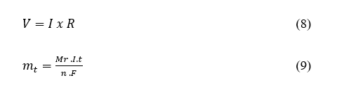
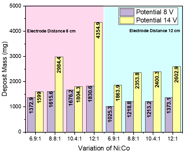
Figure 2 Graphic of mass of deposits in different potentials (8 and 14 V).
As shown in Table 2, a deposited mass of 4,354.9 mg was obtained at an applied potential of 14 V. This result is consistent with the findings of Sudibyo et al. [11], who reported that increasing the potential leads to higher metal deposition [11]. The increase in deposited mass at higher potential is attributed to the enhanced rate of metal ion reduction at the cathode due to greater current flow. However, excessive potential can induce overpotential effects, triggering the hydrogen evolution side reaction and thereby reducing the energy efficiency of the electrowinning process. The data indicate that a potential of 14 V produced a greater deposited mass compared to 8 V under all conditions. Furthermore, cobalt was more readily reduced than nickel because it possesses a lower standard reduction potential [13,23]. At low potential, the reaction rate is limited due to lower electron flow, whereas at higher potential, the accelerated hydrogen evolution reaction may reduce overall process efficiency [21].
XRF characterization of the deposits revealed that the applied potential had a significant effect on the composition of nickel and cobalt (Figure 3). The cobalt content increased with higher potential, as Co2+ ions are more difficult to reduce than Ni2+ ions and therefore require greater energy input (E0 Ni2+/Ni = –0.257 V vs SHE; E0 Co2+/Co = –0.280 V vs SHE). Consequently, increasing the voltage promoted the reduction of cobalt, which was less favored at lower potentials. In contrast, the highest nickel percentage was obtained at 8 V since nickel, having a more positive standard reduction potential, is more easily reduced at lower voltages [11,13]. These findings indicate that increasing potential not only enhances the total deposited mass but also influences the reduction selectivity between nickel and cobalt.
Figure 3 Ni (a) and Co (b) content in the deposits in different potentials.
Effect of electrode distance factor on nickel and cobalt deposition response
The electrode spacing exhibited a significant influence on the deposited mass during the electrowinning of nickel and cobalt (Figure 4). Eq. (10) shows the theory of solution resistance, where κ is the conductivity of the solution and A is the surface area of the cathode. According to the solution resistance theory, increasing the distance between electrodes leads to higher electrolyte resistance, thereby reducing the rate of ion and electron transfer Eq. (10). Consequently, the metal ion reduction becomes slower, requiring a higher potential to maintain the same current. However, this higher potential also decreases the overall energy efficiency of the electrowinning process [24]. As shown in Table 1, the deposited mass decreased as the electrode distance increased. At an electrode spacing of 8 cm, the average deposit mass was approximately 2.4 g, while at 12 cm it decreased to around 1.87 g. This downward trend was most prominent at 8 V, where electrode spacing showed a strong inverse correlation with the deposited mass, as illustrated in Figure 5.
Figure 4 Graphic of mass of deposits over different electrode distance of 8 and 12 cm, (a) 8 V and (b) 14 V.
Electrode spacing has a significant impact on the electrowinning process through the mechanism of solution resistance. Increasing the distance between electrodes leads to higher electrolyte resistance, which in turn decreases the energy efficiency of the process. Elevated resistance reduces the current flow, thereby lowering the metal deposition rate at the cathode [25]. Experimental results indicate that the optimal electrode spacing for the Ni-Co electrowinning system is approximately 8 cm, providing a balance between efficient ion transfer and energy consumption. When the electrode distance was increased to 12 cm, both the deposit mass and recovery efficiency decreased due to the weakened electric field and higher cell resistance. However, excessively short electrode spacing can promote dendrite formation and increase the risk of short-circuiting [25]. In this study, an electrode spacing of 8 cm produced a higher deposit mass compared to 12 cm.
XRF characterization results under varying electrode spacing revealed a significant difference in composition between 8 and 12 cm (Figure 5). The nickel percentage decreased with increasing electrode distance, while cobalt content tended to rise at 12 cm. At 8 cm spacing, lower solution resistance enhanced mass transfer and facilitated nickel ion reduction, resulting in higher deposition efficiency. Conversely, increasing the electrode distance led to greater solution resistance and reduced reduction efficiency, thereby decreasing the nickel fraction in the deposit [25].
Figure 5 XRF data of (a) Ni and (b) Co content obtained from different electrode distance.
Effect of concentration of nickel factor on nickel and cobalt deposition response
In addition to potential and electrode distance, the metal ion concentration in the electrolyte is a critical parameter in the electrowinning process, as it governs the deposition rate, current efficiency, and the composition of the deposited metals, is shown in Figure 2. A higher concentration of metal ions enhances the conductivity and ion mobility within the electrolyte, thereby facilitating the reduction of metal ions to metallic form on the cathode surface [19]. The variation of Ni:Co concentration ratios exhibited a noticeable increase in the deposited mass. At the Ni:Co ratio of 12:1, the highest deposited mass of 4,354.9 mg was obtained under the conditions of 14 V potential and 8 cm electrode distance.
The XRF characterization results revealed a significant variation in the percentage of Ni and Co with different concentration ratios [24]. As shown in the results, the Ni percentage decreased as the Ni concentration ratio increased, is shown in Figure 5. Meanwhile, the highest Ni content in the deposit was observed at the lower Ni ratio of 8.8:1. Increasing the metal ion concentration accelerates ion diffusion and mobility, allowing Co2+ ions to be more readily reduced at the cathode surface. Conversely, at lower metal concentrations, the slower ion transport rate limits Co2+ reduction [24]. The decrease in the percentage of nickel at increasing nickel concentrations is due to anomalous codeposition between nickel and cobalt. Cobalt on the cathode surface will inhibit nickel deposition, thus reducing the efficiency of nickel deposition [26]. This is also due to the influence of current density and electrode distance.
Characterization of deposits
The XRD characterization results (Figure 6) show differences in intensity between electrowinning conditions 1 and 9 (with variation potential 8 and 14 V), as shown in Figure 6. The XRD results from conditions 1 and 9 show main peaks at angles of 44.211° (111), 51.555° (200), and 75.960° (222), coming from Ni FCC [27]. In condition 1, the peak at an angle of 22.269° is a minor and broad peak. Based on the research by Hall D et al., the peak at an angle of 22.269° is a minor peak of the α-Ni(OH)2 phase, which has low intensity [28]. The peaks in the diffractograms of conditions 1 and 9 show crystallinity results in accordance with JCPDS No. 04-0850 (Ni, FCC) standard for nickel metal with a face-centered cubic (FCC) structure. However, the 2 conditions differ at an angle of 75.960° (222), where condition 1 has a higher peak than condition 9. The increase in potential affects the morphology of the deposit. A higher potential reduces the crystallinity of the nickel deposit because a high potential increases the nucleation rate, resulting in uneven crystallinity [12]. Beside nickel, cobalt also forms on the cathode, which is supported by XRF and EDX characterization. The XRD results show peaks formed at 2θ = 44.45° and 75.8°, which are peaks of cobalt metal crystals with a hexagonal close-packed (HCP) phase, according to JCPDS No. 01-071-4239 (Co, HCP) standard [8,29].
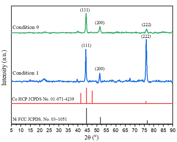
Figure 6 The XRD pattern of condition 1 (8 V) and 9 (14 V).
The observation results of the powder obtained from the electrowinning of a nickel-cobalt mixture under condition 9 are shown in Figures 7. Based on Figure 7(a), the particles deposited on the cathode surface exhibit a flower-like aggregate shape. This morphology is uneven due to the high deposition rate and the effect of overpotential. Analysis with EDX (Figures 7(b) - 7(e)) showed that the flower-shaped aggregate particles were dominated by nickel (86.9%) with a slight presence of cobalt (13.1%). These EDX results indicate that nickel and cobalt were deposited almost in accordance with their concentration ratio, which is 6.9:1. The distribution of cobalt metal is also uniform and surrounded by nickel metal. Therefore, electrowinning nickel and cobalt under conditions of 9 shows that nickel and cobalt metals are deposited evenly and dominated by Ni metal [12]. Nickel and cobalt are deposited evenly due to overpotential, which results in a high current flow, causing Ni and Co metal to be deposited evenly on the cathode [30].
Figure 7 FESEM and EDX of deposit electrowinning condition 9 (a) FESEM, (b) EDX mapping, (c) Ni mapping, (d) Co mapping, and (e) EDX spectrum.
Conclusions
The electrowinning process of mixed nickel–cobalt solutions is strongly influenced by operational parameters such as applied potential, electrode distance, and metal ion concentration. Increasing the potential from 8 to 14 V enhances the deposit mass and cobalt content due to the overpotential effect that accelerates the reduction of Co2+ ions. However, higher potential also induces a side reaction in the form of hydrogen evolution. On the other hand, a shorter electrode distance (8 cm) improves deposition efficiency by reducing solution resistance and increasing ion transfer rate, while higher metal ion concentrations accelerate the deposition rate and affect the reduction selectivity between nickel and cobalt.
Characterization results under conditions 1 and 9 (comparing the potential effect) showed that the deposits were dominated by FCC-structured nickel with a small amount of cobalt. XRD analysis indicated decreased crystallinity at higher potential, while FESEM-EDX revealed non-uniform flower-like aggregate morphology with nickel-dominated composition. Overall, this study confirms that applied potential, electrode spacing, and metal ion concentration play a crucial role in determining the efficiency and selectivity of the electrowinning process. Optimization of these parameters provides a foundation for developing a more efficient and energy-friendly nickel–cobalt recovery process.
Acknowledgements
The authors greatly acknowledge Institut Teknologi Sepuluh Nopember (ITS), Indonesia for funding this work under the Kementerian Pendidikan Tinggi, Sains, dan Teknologi of Indonesia with the scheme of the Doctoral’s disertation (Penelitian Disertasi Doktor) based on contract number 1189/PKS/ITS/2025.
Declaration of Generative AI in Scientific Writing
The authors acknowledge the use of generative AI tools (e.g., Gemini by Google, QuillBot and ChatGPT by OpenAI) for language editing and grammar correction. No content generation or data interpretation was performed by AI. The authors take full responsibility for the content and conclusions of this work.
CRediT Author Statement
Subandrio Subandrio: Conceptualization, Methodology, Writing - Original draft. Nur Lestari Widodo: Investigation, Validation, Writing - Original draft. Andi Mutia Putri Kirana: Methodology, Investigation, Data curation, Writing - Original draft. Ade Irma Rozafia: Writing - Review & Editing. Nur Karimah: Writing - Review & Editing. Nor Farida: Writing - Review & Editing. Wiwik Dahani: Writing - Review & Editing. Afifah Rosyidah: Supervision, Writing - Review & Editing. Wahyu Prasetyo Utomo: Software, supervision, Validation. Djoko Hartanto: Conceptualization, Funding acquisition, Supervision, Writing - Review & Editing.
References
[1] ZF Zhang, WB Zhang, ZG Zhang and XF Chen. Nickel extraction from nickel laterites: Processes, resources, environment and cost. China Geology 2025; 8(1), 187-213.
[2] Q Fan, S Yuan, J Wen and J He. Review on comprehensive utilization of nickel laterite ore. Minerals Engineering 2024; 218, 109044.
[3] W Astuti, F Nurjaman, F Rofiek Mufakhir, S Sumardi, D Avista, KC Wanta and HTBM Petrus. A novel method: Nickel and cobalt extraction from citric acid leaching solution of nickel laterite ores using oxalate precipitation. Minerals Engineering 2023; 191, 107982.
[4] G Acquah, GB Abaka-Wood, J Addai-Mensah and R Asamoah. Selective comminution for upgrading nickel and cobalt in nickel laterite ores. Minerals Engineering 2025; 233, 109667.
[5] MS Moats and WG Davenport. Nickel and cobalt, treatise on process metallurgy: Industrial processes. Elsevier, Amsterdam, 2013, p.575-604.
[6] National Minerals Information, Mineral Commodity Summaries 2025 - RARE EARTHS Data Release: U.S. Geological Survey data release, https://doi.org/https://doi.org/10.5066/P13XCP3R, accessed April 2025.
[7] R Subagja, I Setiawan, AR Rhamdani and J Irawan. Effect of technological parameters on the electrowinning of cobalt from Cobalt(II) chloride solutions. International Journal of Electrochemical Science 2022; 17(9), 220959.
[8] FACM Passos, JDCTD Souza, IDD Santos, R Neumann, PPM Ribeiro and AJB Dutra. Effect of pH and current density on the physical properties of cobalt obtained by electrowinning from sulfate solutions. Minerals Engineering 2024; 211, 108697.
[9] B Amanyazova, M Sailaukhanova, I Kurmanbayeva, A Kylyshbayeva, S Tugelbay, B Tatykayev, Z Bakenov and N Umirov. Advances in battery-grade nickel sulfate production. Separation and Purification Technology 2026; 382, 135672.
[10] T Tawonezvi, D Zide, M Nomnqa, L Petrik and BJ Bladergroen. Selective electrodeposition of Co-Ni alloys from synthetic quasi LiB NMC 532 cathode sulphate solutions using rotating plate potentiostatic electrowinning. Chemical Engineering Journal Advances 2024; 17, 100579.
[11] Sudibyo, A Junaedi, AS Handoko, M Amin, S Sumardi, FR Mufakhir, F Nurjaman, AH Tandoko, and YI Supriyatna. Nickel production from laterites using electro metal electrowinning (EMEW) process. IOP Conference Series: Materials Science and Engineering 2019; 478, 012016.
[12] Y Shi, F Jiang, J Liu, R Wang, Y Zhang, S Xiao, Y Shen, S Mao, X Zhu and S Yang. Simultaneous extraction and separation of Ni(OH)2, Ni powder and Ni plate from waste nickel-cobalt scrap in one spot: Control sequence of electrical reduction. Journal of Environmental Chemical Engineering 2024; 12, 112376.
[13] A Kazem-Ghamsari and H Abdollahi. Electrowinning of nickel and cobalt from Non-circulated Sulfate Electrolyte. Transactions of the Indian Institute of Metals 2022; 75, 1141-1151.
[14] G Alvial-Hein, H Mahandra and A Ghahreman. Separation and recovery of cobalt and nickel from end of life products via solvent extraction technique: A review. Journal of Cleaner Production 2021; 297, 126592.
[15] Y Jiang, CY Chen, TFM Chang, X Luo, D Yamane and M Sone. Electrodeposition of Ni-Co alloys and their mechanical properties by micro-vickers hardness test. Electrochem 2021; 2(1), 1-9.
[16] AI Rozafia, K Roziqin, WP Utomo, YL Ni’mah and D Hartanto. Enhanced electrochemical performance of zeolite/polyethersulfone (PES) composite separator for lithium-ion batteries. AIP Conference Proceedings 2025; 3113, 020054.
[17] N Karimah, AA Mahardika, WP Utomo, AI Rozafia, PAI Afifah, HY Chung, Z Zhu and D Hartanto. Preparation of titanium dioxide/graphitic carbon nitride heterostructure anchored on hierarchical ZSM-5 for synergistic adsorptive and photocatalytic dye degradation. Journal of Molecular Structure 2025; 1335, 141968.
[18] D Hartanto, G Yuhaneka, WP Utomo, AI Rozafia, Y Kusumawati, W Dahani and A Iryani. Unveiling the charge transfer behavior within ZSM-5 and carbon nitride composites for enhanced photocatalytic degradation of methylene blue. RSC Advances 2022; 12(9), 5665-5676.
[19] T Tawonezvi, D Zide, M Nomnqa, L Petrik and BJ Bladergroen. Selective electrodeposition of Co-Ni alloys from synthetic quasi LiB NMC 532 cathode sulphate solutions using rotating plate potentiostatic electrowinning. Chemical Engineering Journal Advances 2024; 17, 100579.
[20] S Sudibyo, L Hermida and PA Reswari. Optimization of electrometal - electrowinning cobalt process from the slag of nickel pig iron (NPI). Journal of Materials Science and Applied Energy 2021; 10(2), 49-57.
[21] A Krishnan, K Archana, AS Arsha, A Viswam and MS Meera. Divulging the potential role of wide band gap semiconductors in electro and photo catalytic water splitting for green hydrogen production. Chinese Journal of Catalysis 2025; 68, 103-154.
[22] E Krause, Nickel and Cobalt. Treatise on process metallurgy. Elsevier, Amsterdam, 2025, p. 497-509.
[23] Q Song, X Du, C Shan, H Xie, Z Ning and K Yu. Effect of magnetic stirring on microstructure of Co deposit in electrowinning. Minerals Engineering 2024; 206, 108522.
[24] Z Liu, X Guo, Z Xu and Q Tian. Recent advancements in aqueous electrowinning for metal recovery: A comprehensive review. Minerals Engineering 2024; 216, 108897.
[25] V Thiagarajan, S Srinivasan, HS Ragav, L Ramesh, P RanjaniS and S Pushpavanam. Scale up of a process for extraction of tin, lead, and copper from waste printed circuit boards by simultaneous electrowinning. ACS Sustainable Resource Management 2024; 1(4), 732-742.
[26] YE Sknar, IV Sknar, OO Savchuk and FI Danilov. Electrodeposition of NiCo alloy from methansulfonate electrolyte. The role of the electrolyte pH in the anomalous codeposition of nickel and cobalt. Surface and Coatings Technology 2020; 387, 125542.
[27] P Li, W Li, Y Huang, Q Huang, J Li, S Zhao and S Tian. Unconventional phase synergies with doping engineering over ni electrocatalyst featuring regulated electronic state for accelerated urea oxidation. ChemSusChem 2023; 16(6), e202201921.
[28] DS Hall, DJ Lockwood, C Bock and BR MacDougall. Nickel hydroxides and related materials: A review of their structures, synthesis and properties. Mathematical, Physical, and Engineering Sciences 2015; 471(21774), 20140792.
[29] M Sharma, JH Jang, DY Shin, JA Kwon, DH Lim, D Choi, H Sung, J Jang, SY Lee, KY Lee, HY Park, N Jung and SJ Yoo. Work function-tailored graphene via transition metal encapsulation as a highly active and durable catalyst for the oxygen reduction reaction. Energy & Environmental Science 2019; 12, 2200-2211.
[30] H Hu, M Tan and L Liu. Anomalous codeposition mechanism of Co-Ni alloy nanowires. Journal of Alloys and Compounds 2017; 715, 384-389.